Explore Our Service,
You Will Love It!
Shoring Contractors in Dubai
Irize is one of the top shoring companies in Dubai for excavation safety, retaining stability, and protection of site integrity. As expert Dubai shoring contractors, we provide robust, engineered, and tailored shoring solutions that support below‐ground excavations, temporary structures, and structural refurbishments without settling for anything less than the UAE’s strict regulations and safety standards.
Our Shoring Services
Irize provides the complete range of shoring solutions designed for every type of project in Dubai – from basement excavations of high-rise buildings to temporary structural support while undergoing facelifts. Our range of services includes:
Retaining Walls:
- Soldier Pile & Lagging
- Sheet Piled Walls
- Contiguous Pile Walls
- Secant Pile Walls
Retaining & Tie-Back Systems:
- Shoring with Ground Anchors
- Shoring with Bracing / Strutting Systems
Diaphragm Walls and Cased CFA piles: For very close, deep support excavation, particularly in intricate ground and groundwater conditions.
Temporary Structural Support: For structures above ground that need renovation, strengthening or where adjacent structures may be affected.
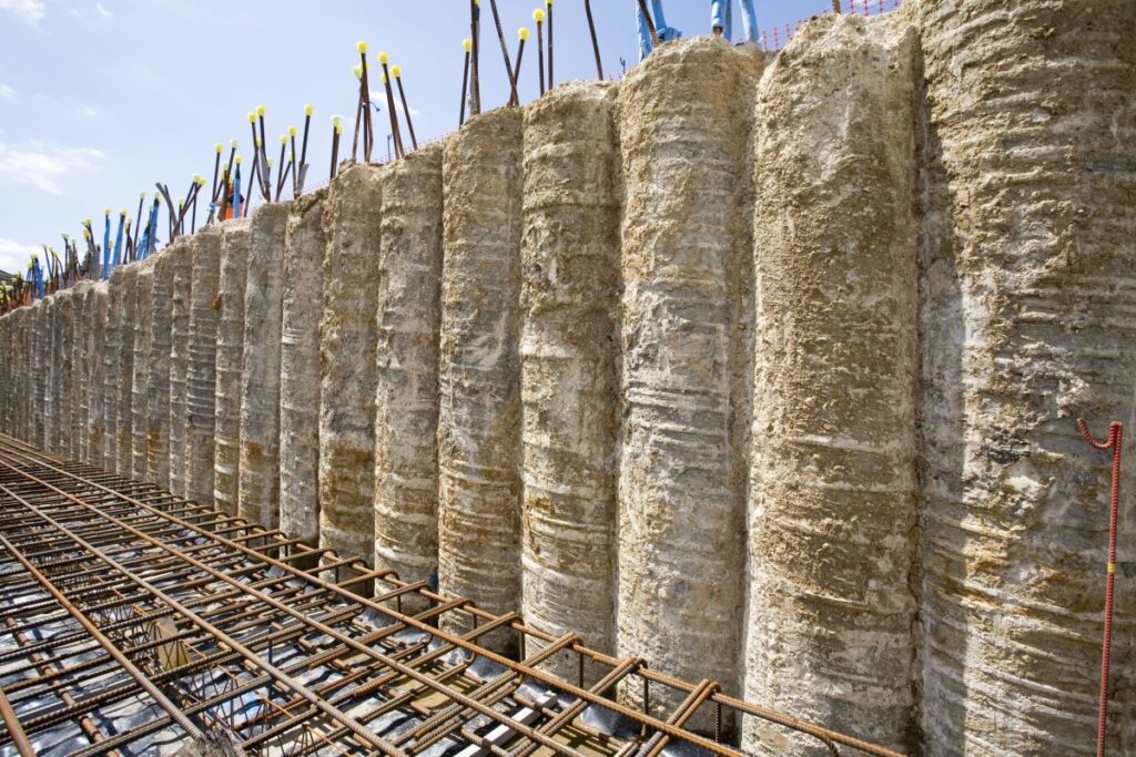
Secant/ Contiguous Pile walls
Secant and contiguous pile walls involve the construction of reinforced and unreinforced piles which may or may not overlap each other to form a shoring wall. This wall can be further supported by ground anchors or internal struts.
The process starts with the construction of a guide beam which sets the template for the piles. This is followed by the construction of unreinforced piles with a gap in between for the construction of reinforced pile later. The reinforced pile is drilled between two unreinforced piles thus creating an overlapping wall of piles with and without reinforcement. Secant pile wall is best suited for soil profile where water level is high or if there are surcharge loads on active sides of the shoring.
Another pile wall system for shoring is contiguous piles which is a wall of reinforced piles closely spaced but not overlapping. Contiguous piles are suitable for soils where water table is not high or is lowered through proper dewatering.
Both systems are further reinforced by the construction of a capping beam connecting them all through one monolithic reinforced concrete beam. Secant and contiguous pile walls also have ground anchors and struts to give them lateral support.
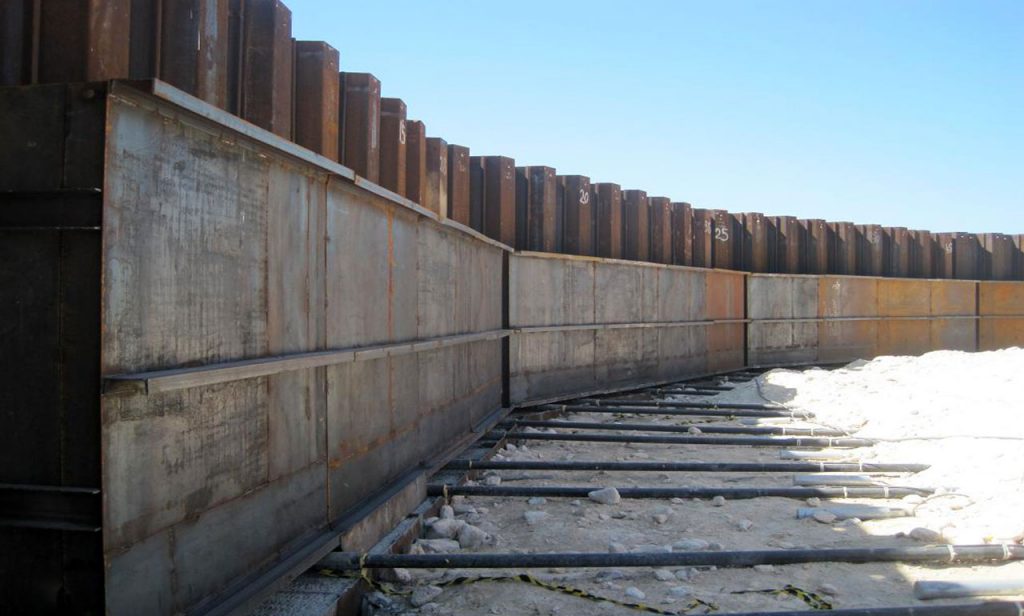
Sheet piles
Sheet piles are prefabricated interlocking steel sheets which are driven in the soil for support low to medium height excavation. Ideal for places where the shoring has space constraint. Anchors can also be provided with sheet piles to provide lateral support if required. Sheet piles are usually inserted by vibratory hammer. In dense or hard soils the insertion of these sheet piles can be a slow process but high frequency vibratory hammers can be useful in such soils. Sheet piles are reusable and can be extracted after the construction proceeds beyond the basement construction.
Steel sheet piling has several advantages over other materials:
1. Provides high resistance to driving stresses due to its shape and material.
2. Sheet piles are light weight, thus easy to handle
3. Sheet piles can be reused on several projects.
4. Sheet piles have long service life above or below water with modest protection.
5. Sheet pile lengths can be easily increased by either welding or bolting
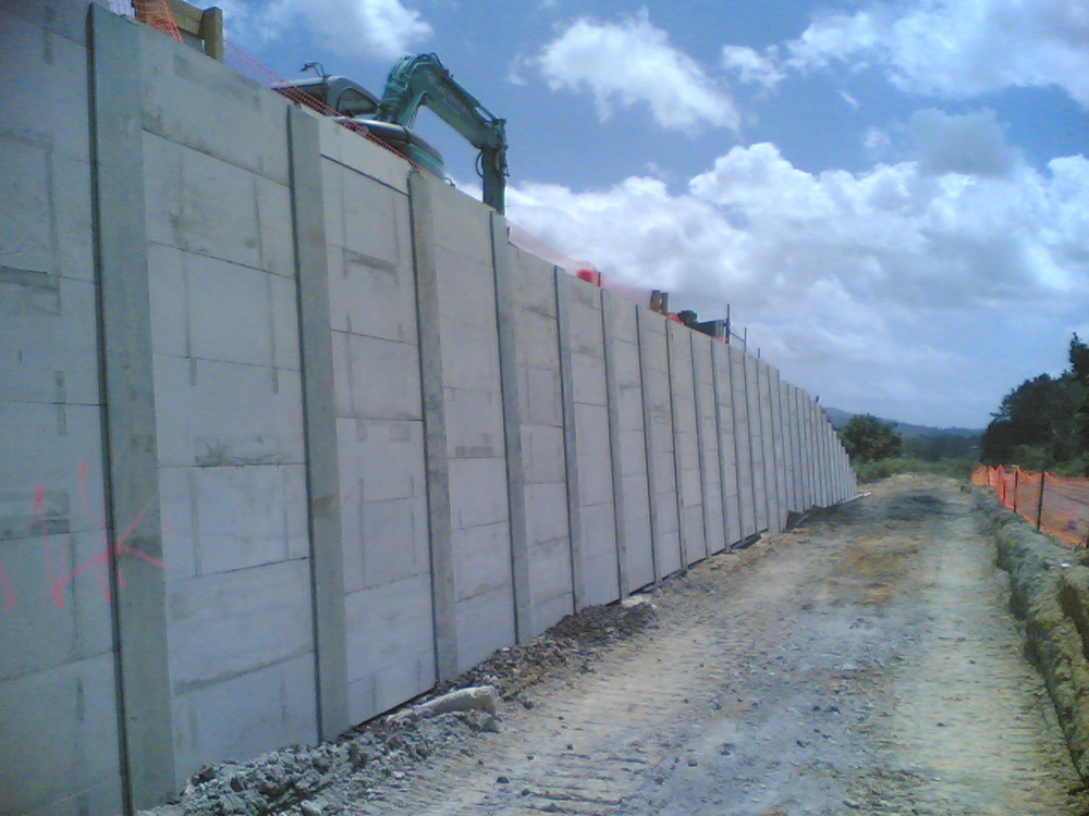
Soldier piles
Soldier piles are I or h beams which are also driven in the soil to have concrete panels or timber planks placed between them to prevent the soil from caving inside the excavation.
Soldier pile and lagging walls are the most inexpensive systems compared to other retaining walls. They are also very easy and fast to construct. The major advantages of soldier pile walls are:
1. Soldier piles take very less time to install.
2. Soldier pile system is a cheaper excavation support system as compared to other conventional methods.
3. Soldier piles can be very useful in areas where service lines are present and can be easily adjusted to repair or move the service lines.
4. Timber or concrete panel lagging can be cheap and fast.
5. Construction of soldier pile and lagging walls does not require very advanced construction techniques.
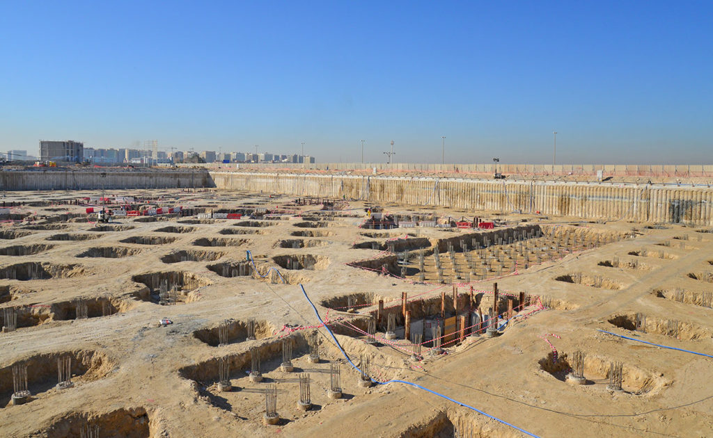
CASED CFA PILES (DOUBLE ROTARY)
Cased CFA piles is a state of the art method for pile installation.
It requires the use of heavy duty large piling rigs with high torque capacities. The method requires the use of two rotary heads driving a heavy duty hollow-stem CFA auger in a clockwise direction into the top soil while at the same time rotating a casing in anticlockwise direction such that the toe of the auger and the bottom of the casing are at about the same level during the advancement of the drilling process. Upon reaching the design pile depth and in a manner identical to CFA piles, the concrete is pumped through the CFA auger but this time constrained by the full length casing. This helps maintain a perfectly circular pile shaft with a very tight control on verticality
DIAPHRAGM WALLS
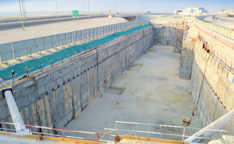
Diaphragm walls are cast-in-situ reinforced concrete walls formed to retain the sides of deep excavation. Diaphragm walls are constructed using state of the art cutters usually suspended from heavy-duty cranes. The thickness and the depth of diaphragm walls are usually design dependant. Our in-house geotechnical design engineers determine the thickness, depth of the wall, level of anchors as well as the amount of reinforcement the wall needs for stability of the designed excavation.
Diaphragm walls are considered to be the most ‘watertight’ type of retaining wall structures. They usually form the external walls of structures such as underground car parks etc. IRBC possesses four diaphragm wall units in the form of 3 cutters (Bauer BC32 and BC40 units) and a Leffer hydraulic grab.
STRUTTING SYSTEM
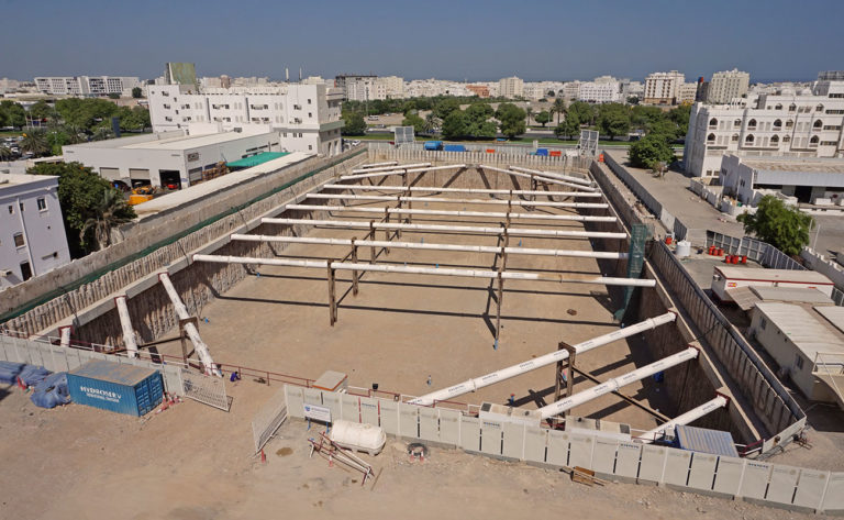
Struts are bracing pipes or steel beams that act to prop the internal sides of an excavation.
Struts are bracing pipes or steel beams that act to prop the internal sides of an excavation. They are usually used in combination with anchors to provide tie-back systems of deep excavations. Struts are generally used when then installation of anchors are not possible due to their potential interference with service corridors or with the foundations of adjacent structures.
GROUND ANCHORS
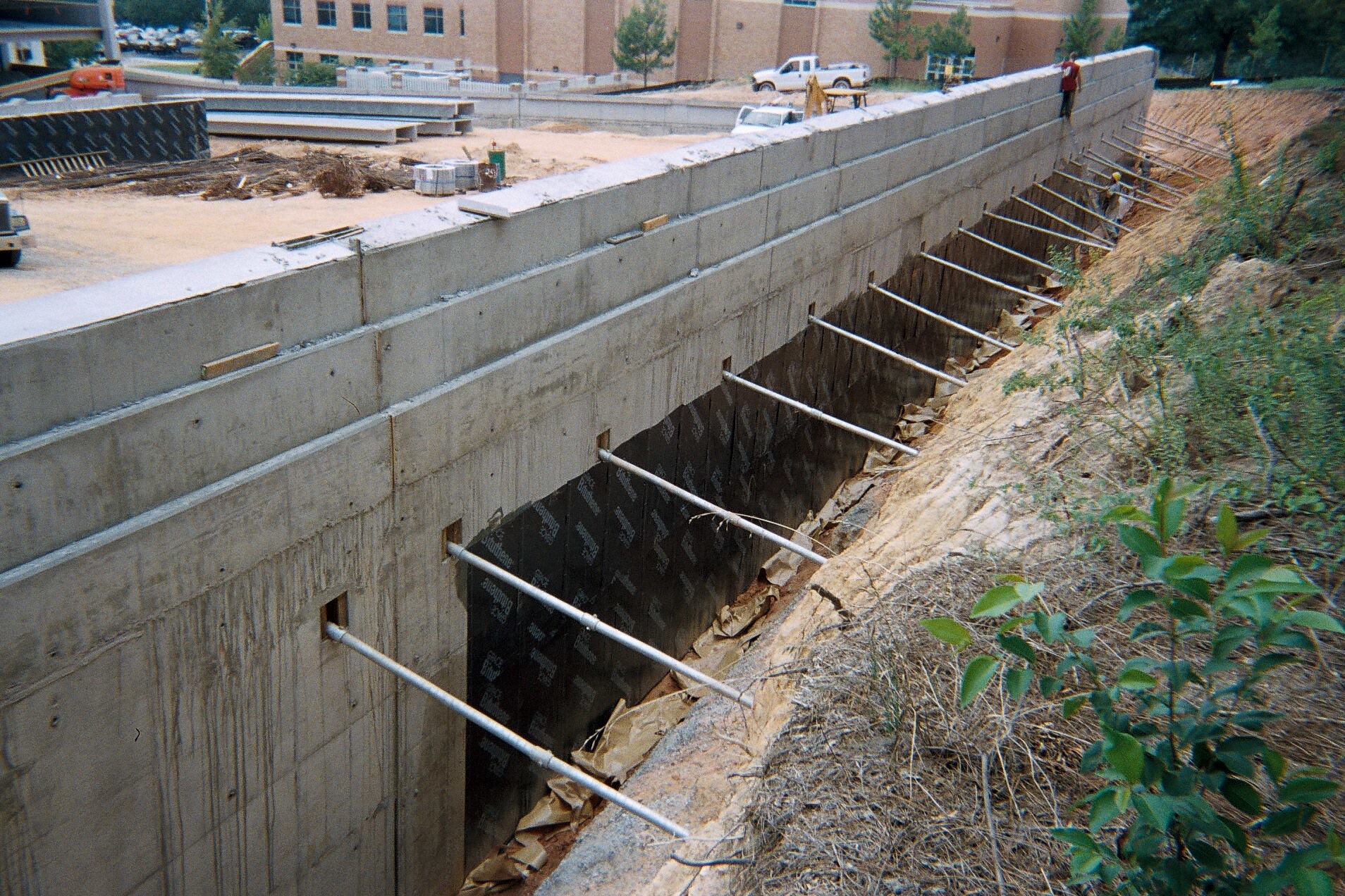
Anchors are inclined tie-backs that act to provide pulling forces to assist earth retaining structures with a reaction force away from the excavation side. Anchors enable the construction of deeper excavation and sometimes multiple layered anchors are needed to support deeper excavations.
Anchors are grouted elements produced in the subsoil by injecting grouting mortar around the rear part of a steel tendon. The grout body is connected via the steel tendon and the anchor head to the structure or the rock section to be anchored.
Why Hire Irize as Your Shoring Contractor
As one of the shoring contractors in Dubai, Irize has established itself for providing safe, consistent, and effective support systems. Here’s why:
Engineering Skill & Compliance: We work closely with geotechnical consultants and engineers to design shoring that is suited to your site’s boundary conditions, structural loads, groundwater table, and soil profile. All our engineered designs are compliant with Dubai Municipality, DDA, and other regulatory body requirements.
Safety & Quality Focus: Safety is non-negotiable. Our site teams employ strict safety practices, frequent inspections, and superior quality material. We ensure structures are stable at each stage – excavation, construction, and backfilling.
Local Know-How: The types of soils in Dubai, water levels, climate, neighbor sensitivities to structure, and requirements for permits can be vastly different. Irize has worked in many districts, boroughs, and development areas, and therefore we understand what it requires and what it does not.
Our Process
Site Investigation & Ground Survey: Determine soil stratigraphy, ground levels, adjacent buildings, and loading.
Design & Engineering: Choose appropriate shoring systems (e.g. contiguous/se cant/sheet pile/struts/anchors) and design detailed structural and method statements.
Permitting & Approvals: Finalize application to Dubai Municipality, relevant authority (DDA, etc.), with full compliance.
Implementation: Mobilize competent teams and plant, set components (piles, sheets, beams, anchors, struts), observe safety and deformations.
Monitoring & Handover: Continuous site monitoring during shoring works; remove or maintain temporary works as required, and handover with certifications and as-built drawings.
Contact Us Today
If you are looking for dependable shoring contractors in Dubai that provide stability, safety, and engineered performance, Irize is your go-to partner. Whether for high‐volume commercial developments, deep basements, infrastructure development, or even minor renovation activities that need structural support, we’ve got you covered.
Reach out to us today for a complimentary consultation, site survey, or quote. Let us guide you in securing your project from the foundation.
